


Foundation Formwork Systems
")
")
")
")
")
")
")
")
")
")
")
")
")
")
")
")
")
")
")
")
")
")
")
Assemply of an formwork type FS 2001 light
Technical specifications type FS 2001 light:
| Element length with overlapping: | 3.5 m |
| Element length actual: | 3.45 m |
| Element height: | according to specifications |
| Profiling of lateral wall: | approx. 10 x 26 mm |
| Push-in brackets: | ø 6 mm |
| Recommendation for bracket distance: | approx.40 cm |
| System components: | 2 (casing + bracket) |
| Weight per sqm | approx. 5 kg |
| Free-standing cement height: | bis 0.4 m |
| Available in radius: | yes |
| Available with base plate laying: | yes |
| Delivery time per casing: | short notice |
| Assembly times: | approx. 0.1 h/qm |
Corrugated profile foundation lateral casing type FS 2001 light
Advantages type FS 2001 light:
- Tremendous amount of time saved
- Uninhibited installation of reinforcements
- Large element length with less weight
- No need for cranes
- No need to sort casing equipment
- Casing element ca be used for internal or external foundation
- The system only consists of side walls and tom and bottom push-in brackets
- Formed parts are manufactured on site with no problem
- No removal of casings
- No transfer of casings
- Short delivery time
System specifications type FS 2001 light:
The system FS 2001 light also consists of only 2 components:
- Corrugated-profile foundation lateral walls for inside and out (same construction)
- Upper and lower spacers (same construction)
MSL uses the name FS 2001 light to describe the thick and shaft-profile model. The foundation was set for this system as early as 1998. With an element length of 3.45 m, the element is 0.4 m longer than the trapezoid-profile model FS 2001.Due the thickness of the material, the weight of the light model per m2 is clearly under that of the trapezoid model and can therefore be erected with no problem even with an element length of 3.45 m by one man. See photo 10.
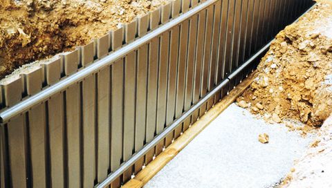
The foundation lateral sections (Photo 2) which are pre-bent at the factory are delivered on palettes. The reinforcement can be installed after the bottom spacers are laid (Photo 5), after erection of the lateral wall with inserted lower spacers (Photos 6, 7) or after erection of both lateral walls, from above. Nailing an anti-penetration strip on the blinding layer has proven to be advantageous. As a result, it is guaranteed that the foundation will run straight on the floor-side. By using squared timber, the casing can be fixed at the top (Photos 6, 8).
Because it is a matter of a lost casing here, we recommend that the casing be propped up by filling it up with dirt in the conventional manner (Photos 9, 10, 11). In the overlap area, approx. every 3.4 m, we commend that the customer secure the elements with 3-4 tapping screws. Formed pieces, e.g. angled elements (Photo 17), are produced quickly and easily by cutting into the cross-sections and bending to required position on site. The system can be supplied with base plate laying. Here an additional cross-section is welded onto the interior of the exterior casing at the plant for insertion into the upper spacer (Photo 14-17).
Photo 18-21 shows how to lay a base plate after concrete has already been poured onto the foundation. Because the base plate was encased with the foundation in one step, there is a major advantage in terms of work time compared to base plates laid in the conventional manner.